An NCU, or Neural Compute Unit, is a specialized processor designed to accelerate machine learning and AI tasks, often used in edge devices and embedded systems for efficient inference.
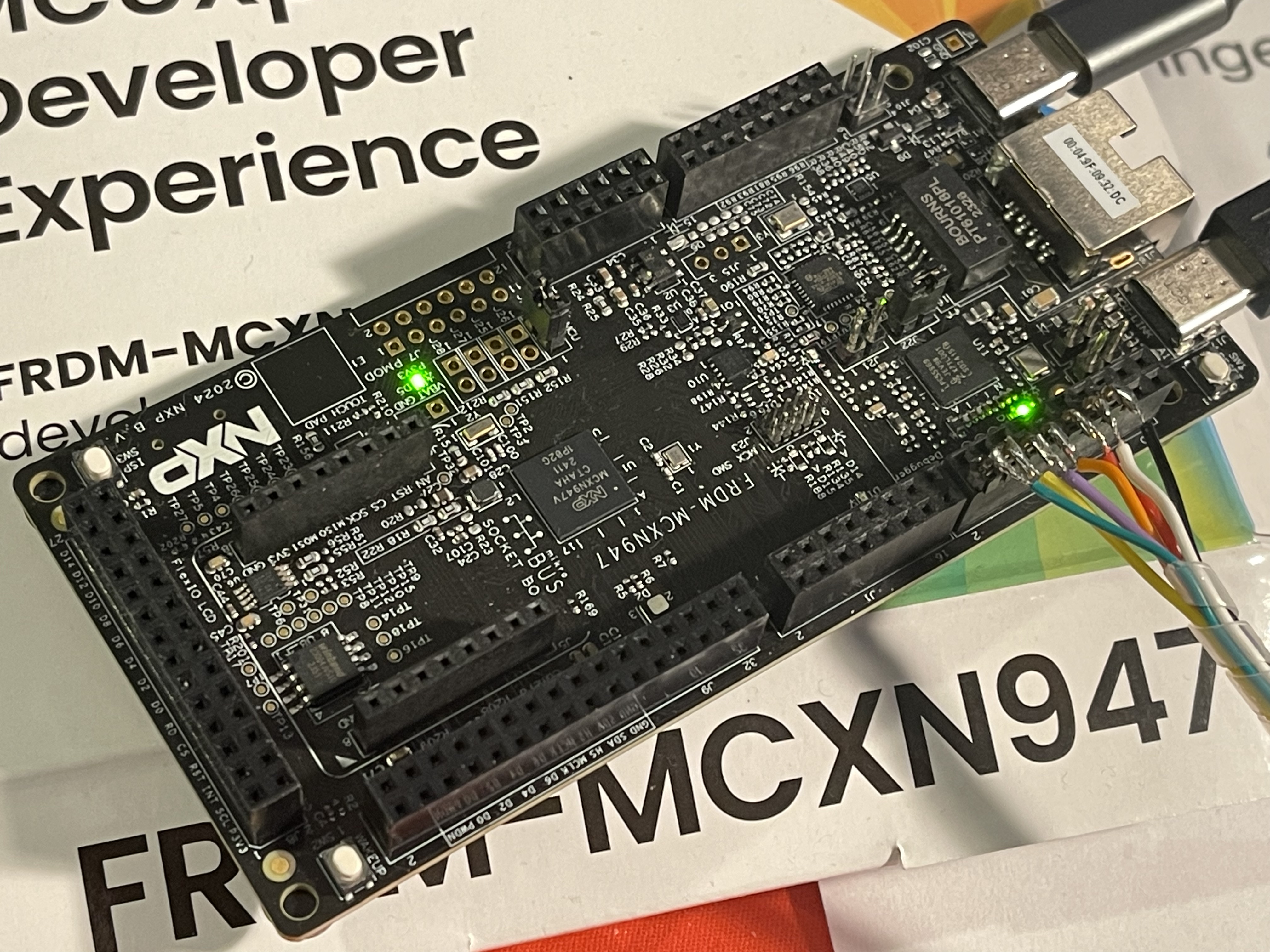
Two weeks ago, I went to the embedded world in Nürnberg and visited the NXP booth. As you may know, I have a LinkedIn Learning course about TinyML on a Raspberry Pi Pico. Because of this, I was interested in the latest AI chips for microcontrollers, such as Neural Processing Units (NPUs). NXP offers the FRDM-MCXN947 development board with an NPU.
Use Case
The FRDM-MCXN947 already includes some AI examples, such as CIFAR-10. But I wasn’t interested in image recognition. I’ve been making my own keyboards and have been curious about magnetic switches. Traditional switches are simple — they are either on or off. Magnetic switches, on the other hand, provide analog values, giving more options. With some AI, this might be interesting.
But for this project, I chose classical switches and a keyboard with only five keys. To cover all letters of the English alphabet, I need to use combinations of these keys. The following picture shows them, including the space key.
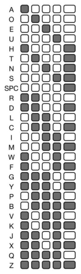
As you can see in this example to get a ‘G’ I need to press the first three keys and for a ‘R’ the first two keys.
Setup
The advantage of five keys is that I had to solder only five keys. The disadvantage is the typing. For this project, I needed to read GPIO data to get the keys’ input. To control an LED, I needed to write GPIO data. There is a HID example that allows me to send letters via USB to a computer. The CIFAR-10 example was useful to have an AI example. For my keyboard prototype, I just needed to combine all software parts.
Disclaimer: Using AI for this task is overkill. A few ‘if’ statements could do the job faster. Also, typing with only five keys isn’t practical for writing long texts like this blog post. That’s why I switched to a different keyboard (with 27 keys).
In my setup, the five keys are inputs, and there are 32 (2^5 = 32) possible outputs. Even though not all key combinations are used, I had to define them. In most AI projects, the system learns to identify unknown inputs, like recognizing new images. Here, all the combinations must be known beforehand. Otherwise, some combinations could give random results, or some letters wouldn’t be available. So, this AI setup is not a typical one.
I used a simple fully connected neural network as the model. I can also add extra layers to make the model larger and to test if the combination recognition is still fast enough. On the other hand, it takes forever to find the right combination, especially in the beginning — enough time for the model to find the correct letter.
I also defined a Convolutional Neural Network (CNN), but this model didn’t reach an accuracy of 1.0, which is fine in this case because only an unmapped key combination was recognized as another unmapped key combination. In this case, it shouldn’t be a problem to use the model.
Training and Code
For the training, I used 1,000 epochs. Depending on the model and its size, the training reached an accuracy of 1.0 at around 500 epochs. The CNN model stuck at an accuracy of around 0.96. The following table shows the accuracy, training times, and inference times for each model.
| Model Name | Layers | Accuracy | Training Time | Inference Time |
|---|---|---|---|---|
| Fully Connected NN | 1 (64 nodes) | 1.0 | 13.97 seconds | 201 us |
| Fully Connected NN | 2 (+128) | 1.0 | 15.66 seconds | 773 us |
| Fully Connected NN | 3 (+64) | 1.0 | 15.84 seconds | 1117 us |
| CNN | 0.96 | 33.16 seconds | 509 us |
As you can see, the inference time is fast enough.
Convert Model
The final step in my Jupyter Notebook was to convert the model into C code and save it as a data array in the model_data.h file. This file is used by the TensorFlow implementation on the MCU.
Let’s see how the TensorFlow Micro code works:
- TensorFlow loads the model from the converted file
model_data.h, which is part of the build process. - Based on the loaded model, the input and output tensors are defined.
- In an endless while loop, the status of the keys is read, provided as input data, and converted into tensor inputs.
- With this input data, the inference runs and predicts the letter.
- The output tensor with the predicted letter is read and sent as a key code to the computer.
I’m using Dvorak as my keyboard layout, so I need to map the predicted value to a corresponding QWERTY letter.
MCU Software
The tricky part was identifying all the pressed keys. Even if you try to press all keys at the same time, one key will always register slightly faster or slower. To handle this, I used a counter. When the first key is pressed, the counter counts up, and after a certain number, the program reads the status of all keys and uses the values as inputs for the model. At this stage, the LED turns off, signaling that something happened.
Keyboard Case Design
Designing the keyboard case was straightforward. I used the Keyboard Layout Editor to define the layout and went with an ortholinear design. The AI03 plate generator converted the layout into a DXF file. Note: AI03 is a keyboard designer and is not related to artificial intelligence :)
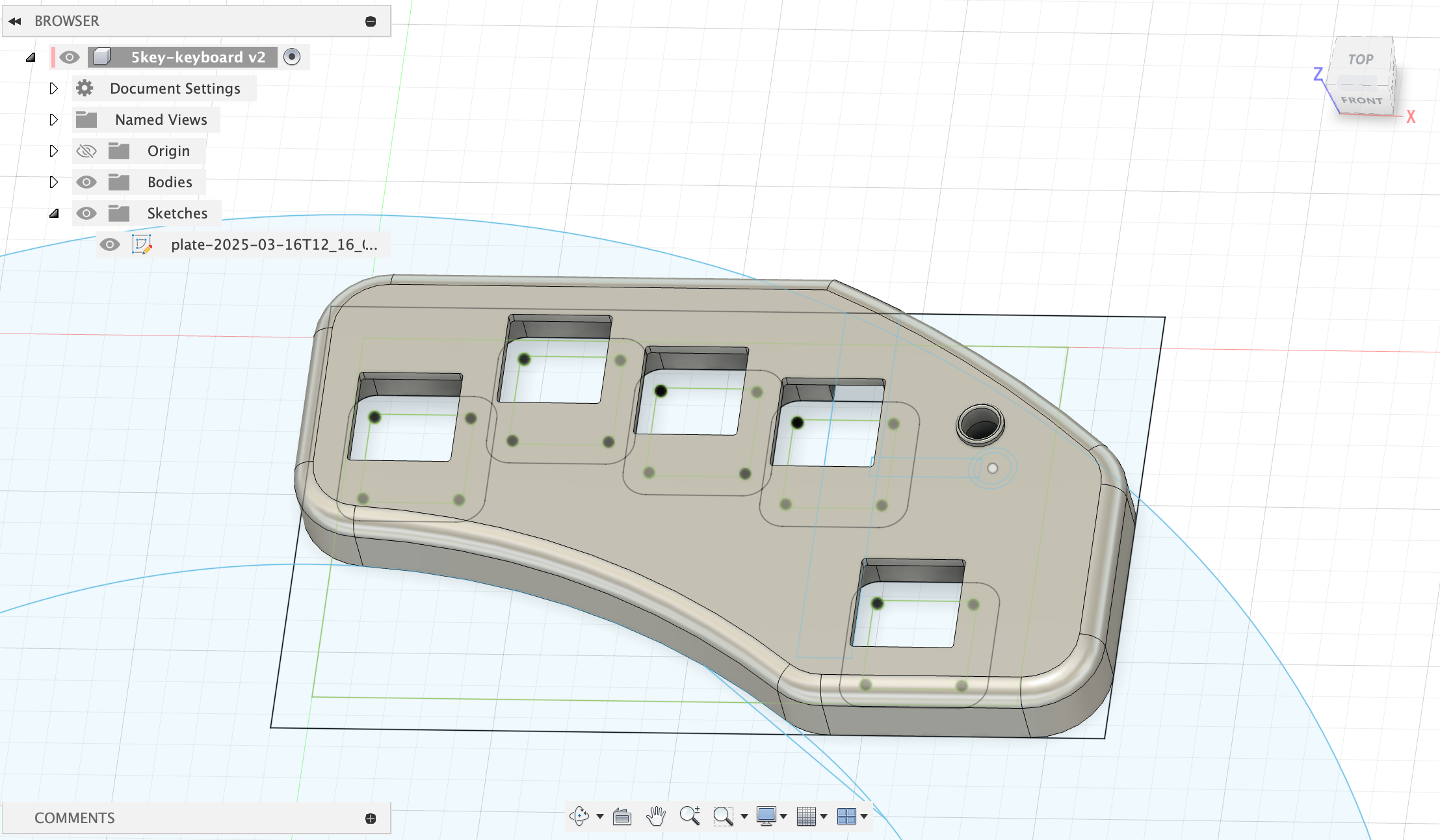
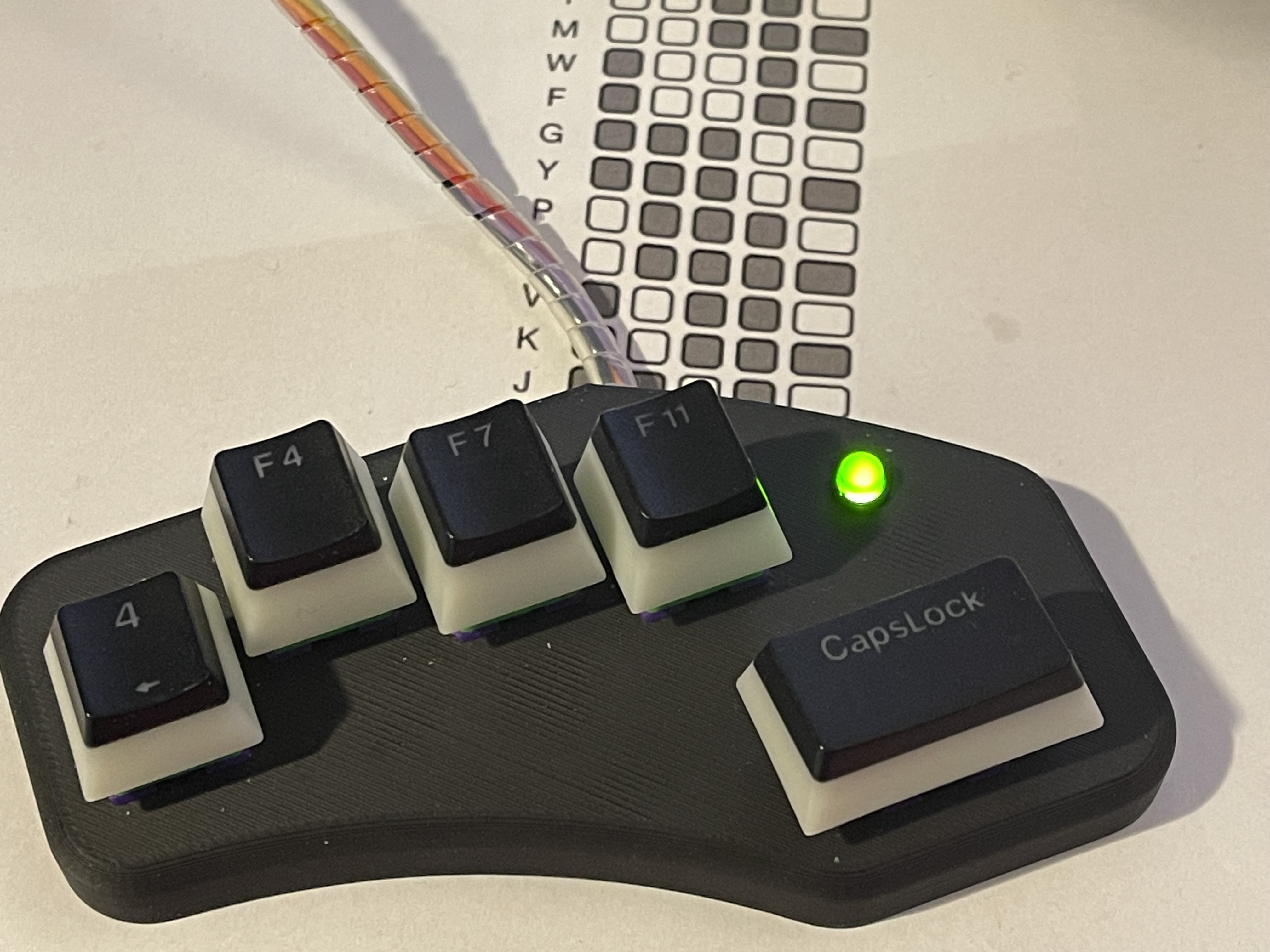
Based on the DXF file, I could design the keyboard with Fusion 360 and then 3D-print the case. At the end, I soldered five keys and the LED and connected everything to the board.
Typing Experience
I am using Dvorak as my daily keyboard layout. This has the advantage that the most-used keys are on the home row. Therefore, eight of the most-used keys are easily accessible with my keyboard. The other key mappings (as you can see in the cheat sheet) focus on frequently used keys. This might need some adjustments because pressing all keys together with the spacebar results in a ‘Z’ and without it in a ‘Q’. This combination is easy to remember but not commonly used.
After some practice, typing became easier, but it will take time to get fully comfortable. I also need to add a backspace key —maybe I should place Q and Z somewhere else.
Summary
I wrote this blog post using keyboards with 5, 27, and 65 keys. It was a fun project, especially when I wrote the first text with the keyboard. As I mentioned, the AI part is oversized, but it was a good experience and learning opportunity. Combining different parts with GPIO, HID, and AI together makes it interesting. And this keyboard has an old-school LED.
You can find the example code and Jupyter notebook on GitHub.